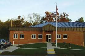
851 Graffius Road York, PA 17404
(717) 292-4911 fax (717) 292-6889
E-mail: cjordan@dovertownship.org
This facility is a regional plant that processes sewage from parts of Dover, Conewago, Manchester and West Manchester Townships. The plant is owned by the Dover Township Sewer Authority and operated by the Dover Township Board of Supervisors through a leaseback agreement. Intermunicipal agreements exist between Dover, Manchester, Conewago, and West Manchester Townships. In 1982, a Joint Advisory Board was established with representatives of the user townships. The original plant was built in 1972 as a 1.75 million gallon per day contact-stabilization plant with secondary removal requirements. Hydraulic overloading compelled the expansion of the plant in 1986 to a 3.5 million gallons per day capacity. The treatment requirements were also expanded to include some nutrient removal, specifically ammonia and phosphate. In 1989, the plant was rerated to 4.0 MGD capacity. In 1997, the plant was again expanded to double its capacity (8 MGD). This expansion was required to meet the demands of the new State and Federal sludge disposal regulations, the Chesapeake Bay requirements, and the capacity demands within the user townships. In 2000, the US government, Pennsylvania, Maryland, Virginia, the District of Columbia, and the Chesapeake Bay Commission promised to work together to clean up our waterways enough to get the Chesapeake Bay and its rivers off the EPA’s “dirty waters” list by 2010. This mandate resulted in permit changes and a $12 million plant upgrade, completed in 2011 to remove additional phosphorous and nitrogen in the treatment process.
SEWAGE or wastewater is the contaminated water from homes, schools, and businesses. It comes from toilets, showers, clothes washers, dishwashers, etc. The contaminants include fecal matter, urine, soaps, detergents, food particles, hair, rags, paper, toys, dead goldfish, and anything else that is disposed in a drain. A person creates an average of 80 to 100 gallons of wastewater every day. Sewers are a network of pipes that bring the sewage to the treatment plant for treatment. Treatment is the continual process of removing the contaminants from the wastewater and then processing the removed contaminants into a product that can be safely recycled.
THE TREATMENT PROCESS consists of a sewage grinder, pumps, grit removal systems, Biological Nutrient Removal Carrousel systems, final clarifiers, and ultraviolet light disinfection. The removed contaminants are thickened, aerobically stabilized, and dewatered prior to disposal.
-
- INFLUENT PUMP STATION: All sewage enters the plant through a 48” diameter precast concrete pipe. It then flows through an influent grinder unit which consists of a horizontally rotating screen that directs all the solids towards and into a dual counter-rotating shaft grinder. The material then flows into the influent wet wells. Submersible pumps move the sewage to the grit removal units.
- GRIT REMOVAL SYSTEM: The raw sewage from the influent pump station is discharged into an aerated grit tank. Compressed air from the blowers, supplied by diffusers, bubbles through the sewage to provide the velocity and roll needed to keep the lighter organic matter in suspension and allow the heavier grit to settle to the bottom. The grit is composed of sand, gravel, egg shells, bits of glass, etc. It is removed by a series of airlift pumps and separated from the wastewater by a screw-type classifier.
- FERRIC CHLORIDE: A solution of Ferric Chloride is added to the aerated grit tanks to aid in phosphate removal. The precipitated phosphates are removed with the biosolids increasing its values for land utilization.
- OXIDATION DITCHES (BNR): This is the biological “heart” of the treatment process. The degritted sewage mixes with the mixed liquor, a super-rich solution of microorganisms, including bacteria and protozoa. The Carrousel A2C System recently completed is an advanced secondary wastewater treatment process designed for biological nitrogen and phosphorus removal. The System is a staged, activated sludge process which enhances the biological removal of nutrients such as nitrogen and phosphorus through the use of aerobic, anoxic, and anaerobic zones. Air is mechanically added by the mixing action of the aerator vanes. This creates an aerobic zone. As the mixed liquor flows away from the aerator, the amount of free dissolved oxygen decreases until it enters an anoxic zone of no dissolved oxygen. This forces certain microbiological species to use chemically bound oxygen, thereby continuing the nitrogen removal process. Part of the mixture is diverted to the clarifiers, while the rest of the mixed liquor continues to flow around the carrousel loop and carry on the microbiological treatment process through the anaerobic, anoxic and aerobic stages.
- CLARIFIERS: Five clarifiers are used to settle solids from the oxidation basin mixed liquor. The mixture enters the tank through a vertical pipe in the center of each clarifier. As the flow proceeds toward the outer rim, the solids settle out in the bottom of the tank and the clear water flows out over the weir. The solids are called RAS (Return Activated Sludge). The RAS is concentrated mixed liquor that is full of hungry microorganisms. The RAS is pumped back to the beginning of the oxidation tanks so that the incoming sewage is devoured by the hungry microbes, continuing the cycle. The clear overflow from the clarifiers, called effluent, flows to the UV tanks for disinfection.
- DISINFECTION: This is a process that destroys disease-causing organisms in the treated water before it is discharged into the Little Conewago Creek. From 1972 to July 1997, chlorine gas was used as the disinfecting agent. Chlorine is very effective in chemically killing microbes. However, it can produce harmful byproducts, such as chloro-organics, which are known carcinogens. On-site storage of chlorine gas in ton containers was also a community safety issue. An evacuation plan for a five mile radius is required if large quantities of chlorine gas are kept on the plant site. With these issues in mind, the Dover Township Sewer Authority eliminated chlorine usage at the plant. It was replaced by Ultraviolet Light Disinfection (UV). Microorganisms in the water are exposed to the UV light as they pass by special lamps submerged in the effluent. This light penetrates the cell walls and disrupts and destroys the DNA within bacteria, viruses, and protozoa, eliminating their ability to reproduce and cause infection. UV is a simple, chemical-free, environmentally friendly, and highly effective method to disinfect the treated effluent prior to discharge to the receiving stream.
- SLUDGE TREATMENT & BIOSOLIDS The microorganisms in the oxidation ditches reproduce as they breakdown and assimilate the organic matter in the sewage, producing excess solids in the system. These excess solids, called sludge, are removed from the system by diverting a portion of the return activated sludge to one of two thickener tanks. These units are cylindrical tanks with coned bottoms which allow the solids to settle. The thickeners concentrate the sludge from less than 1% to 2% solids content. The water which separates from the thickened sludge flows back to the beginning of the plant for reprocessing. The thickened sludge is pumped into one of three digesters, where it is mixed and aerated until it becomes stabilized. The mixing and aeration is accomplished by a series of diffusers positioned along the bottom of the tanks. Air is supplied to the diffusers through positive-displacement blowers. The stabilized sludge, called biosolids, must meet many strict State and Federal requirements before it can be applied to farmland. The liquid biosolids are pumped to the centrifuges where it is dewatered to approximately 20% solids concentration. The dewatered biosolids have a look of damp rich soil and has an earthy/slightly musty odor.
- LABORATORY An important part of the treatment process is the laboratory. The quality and quantity of the effluent water discharged from the plant is defined in a permit issued by the US Environmental Protection Agency and the Pennsylvania Department of Environmental Protection. Daily testing of the plant effluent is required to verify that permit conditions are being met. The lab also has the responsibility to perform many operational analyses that keep the operators informed of conditions within the treatment process. This allows for the optimization of treatment capabilities of the system and assists in controlling the costs of operations. The laboratory is certified by PADEP for the permit-required analyses.
- CONTROL & DATA SYSTEM A state-of-the-art process control system consists of motor control centers, control panels, instrumentation, and a programmable logic controller (PLC) system. The PLC system consists of Logix processor backed by Ethernet/IP processors. The PLC is networked to desktop computers which are running Wonderware process control software on a Windows platform.
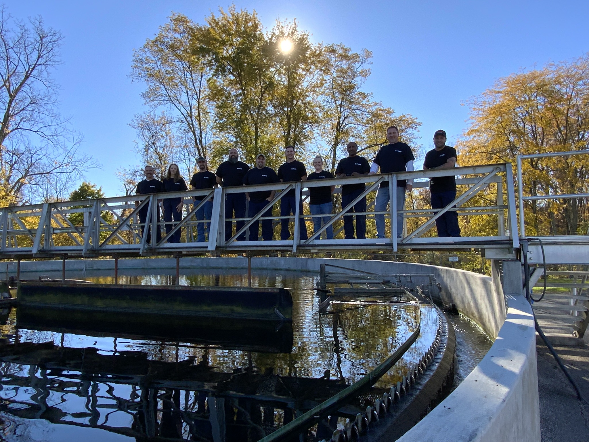
- STAFFING The daily operations of a treatment plant requires the work of highly skilled employees that work as a professional team to optimize the treatment process, safeguard our environment, and protect the financial investment the community has made to the facility. Laboratory personnel monitor the progress of the treatment process and run analyses to ensure the regulatory requirements are being met. Operators and maintenance personnel keep the treatment process functioning efficiently and continuously. The community has millions of dollars invested in the construction, maintenance, and operation of this facility. The staff protects this investment and insures the continuous performance of the system to enhance the water quality of the Little Conewago Creek and its ecosystem.
More WWTP Information


